 Bars
Bars
 Beads & Spheres
 Bolts & Nuts
 Crucibles
 Discs
Discs
 Fibers & Fabrics
 Films
Films
 Flake
Flake
 Foams
Foams
 Foil
Foil
 Granules
 Honeycombs
 Ink
Ink
 Laminate
 Lumps
Lumps
 Meshes
 Metallised Film
 Plate
Plate
 Powders
 Rod
Rod
 Sheets
 Single Crystals
 Sputtering Target
 Tubes
Tubes
 Washer
 Wires
Wires
 Converters & Calculators
 Write for Us
Gas-Atomized Spherical Powders: Addressing The Technological And Practical Challenges
1. Introduction
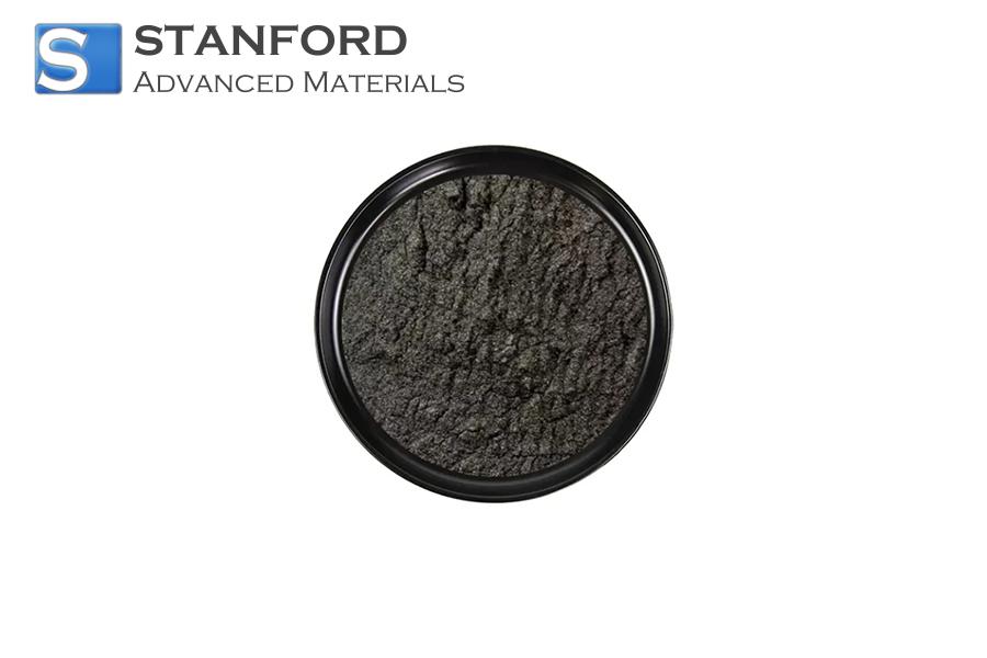
Spherical Metal Powder is used as an important raw material for additive manufacturing (AM) because of its quantifiable homogeneity and flowability, which improve the precision and moulding efficiency of printed parts. It is also amenable to recycling, thereby reducing operational costs and environmental impact.
2 Spherical Powders
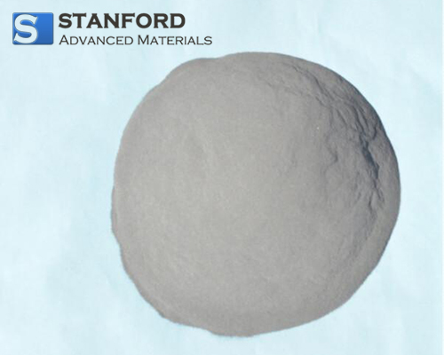
2.1 What is Spherical Powder?
3D metal printing relies heavily on spherical metal powder, which serves as the feedstock and is a key component in the supply chain. The progress in 3D metal printing is directly linked to the development of these powders. The materials currently in use include iron, titanium, cobalt, copper, nickel and various alloys thereof.
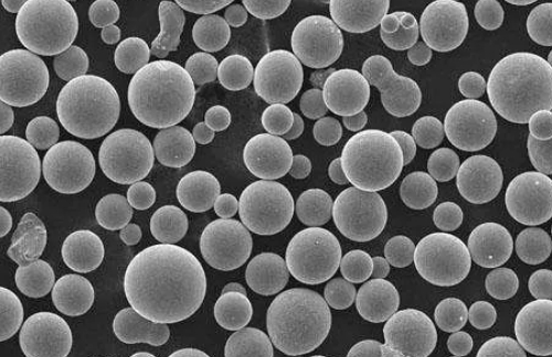
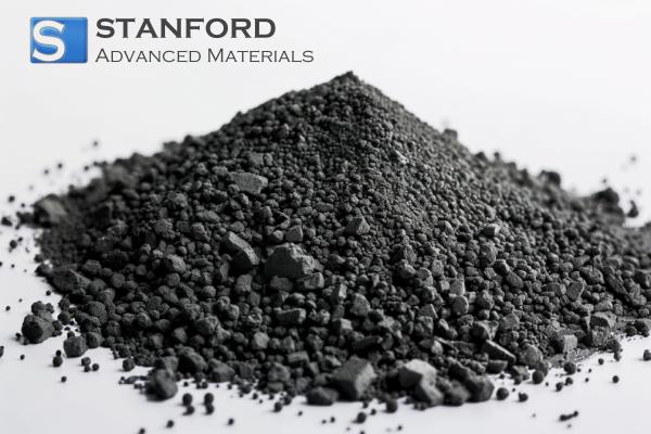
2.2 What are the Characteristics of Spherical Powders?
The defined structure of spherical powder imparts measured properties that are not seen in irregular powders. These powders are used in applications requiring rigour in material structure.
1. High uniformity: The spherical shape yields a narrow particle size distribution. This uniformity in particles during the forming process improves precision and utilises the physical and chemical properties of the material effectively.
2. Compressibility: The compact structure exhibits good compressibility and plasticity, which allows for the preparation of complex material formations and reduces production scrap.
3. Flowability: The uniform particle shape and size distribution result in excellent flowability. This leads to a more efficient production process and lowers processing time and costs.
2.3 What are the Applications of Spherical Powders?
In addition to the aforementioned 3D printing applications, spherical powders are employed in powder metallurgy, as material additives and as catalyst supports.
1. Metal 3D Printing: Spherical metal powder is a vital raw material in metal 3D printing. In processes such as powder bed fusion (e.g. selective laser sintering) and direct energy deposition (e.g. laser melting), these powders provide reliable flowability, packability, high density and precision in the final form.
2. Powder Metallurgy: Spherical powders are used to manufacture metal parts and materials. The ensured homogeneity and flowability contribute to achieving the required density and mechanical properties.
3. Coating and Spraying: Spherical powders are used for the production of coated materials, for instance in thermal spraying, cold spraying and plasma spraying. The uniform particle shape and size distribution helps produce even spray layers and improves coating adhesion and wear resistance.
4. Production of Composite Materials: Spherical powders may be combined with resins, ceramics, polymers and other substances to form composites used for structural and functional components in the automotive, aerospace, construction and other sectors.
5. Catalyst Support: In the chemical industry, spherical powder is frequently used as a support for catalysts in chemical reactions, environmental protection and energy conversion processes.
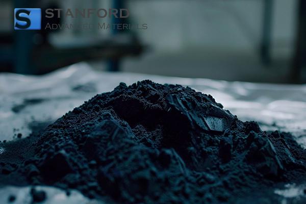
3 Production of Spherical Powder
During aerosolisation, solid powder is atomised into minute particles through gas injection or mechanical vibration, thereby forming an airborne mist. In gas atomisation, a high‐pressure gas stream (typically an inert gas) is used to disintegrate the molten material. Given that the specific heat capacity of gas is lower than that of water, the droplets cool more slowly. Consequently, the powder produced by gas atomisation tends to be spherical, whereas water atomisation generally produces irregular particles unsuitable for 3D printing.
During atomisation, the raw alloy or metal (in any form) is melted in a furnace. The melt is maintained for a period to ensure uniformity. Thereafter, it is transferred into a crucible fitted with a refractory nozzle with a controlled flow rate. When the nozzle opens, the melt enters the atomisation chamber, falls freely and is cooled, atomised and solidified by a high-velocity air stream. Finally, the powder is collected from the bottom of the chamber. A subsequent drying step is then required.
3.1 Inert Gas Atomisation
The principle involves the molten metal stream colliding with a high-speed air current, resulting in rapid cooling and the formation of metal powder. Two main nozzle types are used in gas atomisation: free-fall nozzles and close-coupled nozzles. Free-fall nozzles have a simpler construction and are less prone to blockage; however, their atomisation efficiency is lower. The close-coupled nozzle design is more compact, which reduces the gas travel distance and energy loss, thereby increasing the atomisation efficiency.
3.1.1 Plasma-Inert Gas Atomisation (PIGA)
In this method, the raw material is formed into pre-alloyed rods that are melted using plasma arc heating in a water-cooled copper crucible. The bottom of the crucible is connected to an induction heating nozzle within a ceramic-free nozzle system. This system introduces the molten metal into the gas atomisation nozzle. The method prevents contact between the plasma cannon and the raw material rods during melting, thereby maintaining process purity.
3.1.2 Electrode-Induction Gas Atomisation (EIGA)
The Electrode-Induction Gas Atomisation (EIGA) method is derived from traditional gas atomisation techniques. Instead of using a crucible to contain the molten metal, rotating metal rods are used as the primary raw material. These rods are melted by induction heating, and the molten metal is fed directly into the atomisation chamber. This configuration avoids any contact with a crucible during melting, thereby preventing contamination and ensuring a high degree of powder purity.
EIGA offers several advantages, including minimal contamination of the raw material, rapid heating rates, a streamlined process and equipment that is simple to maintain. However, challenges exist:
1. The induction coil limits the diameter of the raw material rod for the induction electrode. Rods of larger diameter require higher power supplies and larger coils, which increases costs and hinders the development of large-diameter rod atomisation.
2. Maintaining a stable interplay between the vertical feed rate and the rotational speed of the rod is complex. This balance is necessary to ensure the rod remains correctly positioned within the coil.
3. Achieving a continuous and stable stream of molten metal during electrode induction is challenging. The atomisation process may produce droplets with incomplete coalescence or partial melting that lead to blockages in the delivery system.
3.1.3 Plasma Atomisation (PA)
In plasma atomisation, plasma is employed as the primary heat source to melt the raw material, which is usually in the form of powder or wire. Once the material is exposed to the plasma, it is simultaneously melted and atomised by inert gas streams. The subsequent processing steps are similar to those of gas atomisation.
Compared with conventional methods, plasma atomisation produces powder with a particle size distribution ranging from 10 to 150 μm, with approximately 40% of the powder being less than 50 μm. The resulting powder also exhibits high sphericity and a minimal level of impurities.
3.2 Centrifugal Atomisation
3.2.1 Plasma-Rotational Electrode Method
In this method, the anode metal rod is mounted on a high-speed rotating shaft and melted by a plasma arc. The molten metal droplets are dispersed tangentially by centrifugal force, then solidify into powder. The process is carried out either in vacuum or under the protection of an inert gas atmosphere[2].
3.2.2 Centrifugal Atomisation with Rotating Disc
Here, the molten metal is spread tangentially in a high-speed rotating disc, and through spheroidisation, the liquid condenses into powder. The average particle size exceeds 100 μm, and it is dependent on the centrifugal speed of the rotating disc[3].
3.3 Plasma Burner Atomisation Technology
This twin-stream atomisation technology employs three plasma burners as the heating source. The raw material wire is heated and melted by the plasma arc and then fully atomised by the high-temperature atomising gas. The melting and atomisation processes occur simultaneously, resulting in an average particle size of 40 μm, which produces a fine powder with high sphericity.
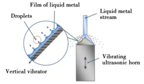
3.4 Ultrasonic Atomisation Method
Powder produced using ultrasonic atomisation is fine, cools rapidly and has a smooth surface with minimal satellite particles. The method utilises the kinetic energy from ultrasonic vibrations combined with an airstream to break the liquid stream. Although this approach improves atomisation efficiency, it still requires a considerable consumption of inert gas.
3.5 Plasma Spheroidisation
Radio Frequency (RF) Plasma is used in the powder spheronisation process. The high temperature provides the energy needed for rapid heat absorption and melting. Under the action of surface tension, the molten material condenses into a spherical form and then solidifies rapidly.
Table 1 Comparison of the Various Processing Methods
|
Method |
Advantages |
Disadvantages |
|
Gas Atomisation |
(1) High powder production efficiency (2) Reliable sphericity (3) A well-established production procedure |
(1) High equipment costs (2) Strict raw material requirements (3) A limited range of powder sizes may be produced. |
|
Ultrasonic Atomisation |
(1) Suitable for specific metal materials (2) No requirement for high temperatures during production (3) Uniform particle size distribution without coarse particles |
(1) Lower powder production efficiency (2) Strict requirements on the particle size of the raw material (3) Special ultrasonic equipment is required |
|
Centrifugal Atomisation |
(1) Ability to manufacture high-purity powders (2) Applicability to various metal materials (3) Good control over particle size distribution |
(1) Lower efficiency in powder production (2) High investment and operational costs (3) Some metals are sensitive to oxidation |
|
Plasma Spheroidisation |
(1) Capability to produce high-purity metal powders in the micrometre range (2) Applicable to various metal materials (3) Can operate at lower temperatures |
(1) High equipment costs (2) Stringent technical requirements for operation (3) Requires control of the gas environment and plasma conditions |
4 Processing Challenges
4.1 Hollow Powder
Hollow powder is a frequently observed defect in atomised powders. Two types of pores are generally encountered: one involves entrapped gas within the droplet that forms closed pores, typically ranging from 10% to 90% of the particle size, most often in particles larger than 70 μm; the other involves pore formation between the dendrites due to contraction during solidification, normally less than 5% of the particle size and distributed both internally and on the surface. In general, as the particle size increases, the frequency, size and gas content of the pores also increase.
The formation of hollow powder is associated with the droplet fragmentation mechanism during the atomisation process. Various fragmentation mechanisms occur simultaneously, dependent on the energy from the interaction between the atomising gas and the molten metal. In one of the most energy-intensive mechanisms, known as Bag Crushing, larger droplets under the influence of the gas stream form bag-like sheets that extend perpendicular to the gas flow. When the liquid viscosity is low, the outer layer of the film breaks to form small droplets; however, if the droplets cool rapidly, their viscosity increases significantly. If the viscosity is sufficiently high, the fragmentation of the liquid film is suppressed, and the openings merge to form a hollow droplet containing entrained gas. Consequently, reducing the energy input during the fragmentation process is necessary to prevent hollow powder formation.
4.2 Satellite Powder
Satellite powder refers to small particles that adhere to the surface of larger particles, forming a satellite-like structure within the powder batch. This phenomenon affects the sphericity, flowability and bulk density of the powder. In addition, the presence of these attached particles may lead to aggregation of larger particles due to adsorption forces and surface tension. This in turn poses complications during subsequent separation processes.
Current research focuses on two main approaches to reduce satellite powder formation. Firstly, careful control of the atomisation process and the molten material’s properties aims to reduce the particle size variance. This measured reduction in size disparity decreases the likelihood of collisions between powder particles and molten droplets. Secondly, the introduction of an additional airflow into the atomisation chamber or the optimisation of chamber design helps to minimise internal airflow turbulence, thereby reducing collision occurrences.
4.3 Control of Powder Particle Size Distribution
Following preliminary sieving, larger particles are removed from the powder. Narrowing the particle size distribution improves overall yield and reduces production costs. The optimisation of the nozzle structure is essential for controlling the size distribution. Schwenck et al. [4] developed a shrink–expand ring-folded nozzle with a throat diameter of 0.8 mm and compared its performance with conventional shrink ring-folded nozzles of 0.8 mm and 0.4 mm. Their measurements indicated that powder produced using the shrink–expand nozzle had a smaller mean particle size. In addition, the geometric standard deviation of particle size was reduced from 2.14 to 1.87, indicating a tighter distribution and increased yield. Furthermore, heating the gas to 320 °C further reduced particle size and distribution, thereby improving yield.
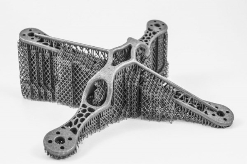
5 Outlook for the Development of Spherical Powder Production Technology
Additive manufacturing (AM) is an advanced rapid prototyping technology using metallic materials to print parts layer by layer based on digital model files. In addition to commonly used plastics, metals and ceramics are used to produce components requiring high strength and corrosion resistance, and biomaterials are employed for medical and biological applications. The properties of additively manufactured products are controlled at a point-by-point level, which reduces macroscopic metallurgical defects and the segregation commonly observed in traditional casting and forging. Furthermore, the conventional constraints regarding alloy compositions in traditional metallurgical processes are alleviated. With the continued refinement of spherical powder processing technology, metal part manufacturing in AM now exhibits higher precision, purity and application suitability. Therefore, the development of spherical powder production technology remains closely linked to advances in additive manufacturing.
6 Conclusion
The quality of spherical powder, as an important raw material for additive manufacturing, has a direct impact on the quality of the final parts. Accordingly, controlling the processing method and enhancing the production technology for spherical powder is of critical importance. Currently, the predominant method for producing spherical powder is based on aerosolisation, whereby solid powder is atomised into fine particles by gas injection or mechanical vibration, forming an airborne suspension. The particles become nearly spherical due to surface tension. The primary issues in this method concern the formation of hollow and satellite powders, while the control of nanoparticle size remains a key factor influencing overall powder quality.
Further Reading:
SPHERICAL POWDERS UNDER THE MICROSCOPIC – HOW PARTICLE SHAPE AFFECTS FUNCTIONALITY
References:
[1] KROEGER J, MARION F. Raymer AP&C: Leading the way with plasma atomized Ti spherical powders for MIM [J]. Powder Injection Moulding International, 2011, 5(4): 55.
[2] Savage S J. Production of rapidly solidified metals and alloys [J]. Journal of Metals, 1984, 36(4): 20.
[3] Leo V M Antony, Ramana G Reddy. Verfahren zur Herstellung von hochreinen Metallpulvern [J]. Hochreine Metalle, 2003, 3: 14.
[4] SCHWENCK D, ELLENDT N, FISCHER-BÜHNER J, et al. A novel convergent-divergent ringular nozzle design for close-coupled atomization [J]. Powder Metallurgy, 2017, 60(3): 198-207.
 Chin Trento
